Manufacturing Improvement Devices, Inc.

Changeover Tool (COT)


Overview

The Changeover Tool is used in the manufacturing environment to guide operators to perform machine changeovers. All machine adjustment points are captured and saved to a configuration on the Changeover Tool once an OEM or an experienced operator optimally adjusts a machine for a given product.

Once the machine has been adjusted, all the adjustment points’ distance values are captured and saved to a configuration on the Changeover Tool. Saved changeover configuration data is then available to all machine operators as a standard. When an operator selects a product for guidance, they will be interactively guided to deliver a flawless adjustment of the machine – first time and every time.

The Changeover Tool can serve a maximum of 5 machines; each machine can be equipped with up to 50 adjustment points. Adjustment points are determined by machine design and customer preference. Once adjustment points are determined, location aware machine brackets are installed to enable COT adjustment guidance at those points. Location aware brackets can be also used for context-aware, on demand training.


Changeover Tool Components

The Changeover Tool consists of 4 main components;

  1. COT Controller:

    The COT Controller is the users interface with the system software. Through the COT software, operators are guided to perform changeover operations.

  2. Calibration Plate:

    The Calibration Plate is used to calibrate the COT Sensor in order to maintain accuracy across multiple Changeover Tools which may be present on the manufacturing floor.

  3. COT Sensor:

    The COT Sensor is a wireless, mobile unit used by the operator to help them perform and verify machine adjustments during a machine changeover.

  4. COT Brackets:

    COT Brackets are components which are permanently installed on the machines to be Changeover Tool enabled. The number of brackets vary based on what adjustments the end user would like to enable guidance on. A maximum configuration is 250 brackets across 5 machines (shown in the table below).

    Machine 1 Machine 2 Machine 3 Machine 4 Machine 5
    Brackets 1-50 Brackets 51-100 Brackets 101-150 Brackets 151-200 Brackets 201-250


Methodology

The Changeover Tool and its components are used by operators to perform machine changeovers. The tablet PC and wireless COT sensor work together to guide an operator to perform a machine changeover.

The following steps are followed to perform a machine changeover using the Changeover Tool:

  1. Bootup / Tag-out Checklist:

    The COT tablet PC is powered up. Once the tablet PC has booted into the MID software, the operator will be asked to confirm that the machine's tag out checklist has been completed to ensure the machine is safe for the changeover procedure.


  2. Sensor Calibration:

    Once the operator has confirmed that the tag out checklist has been successfully completed, they are required to perform sensor calibration. Sensor calibration is performed every start-up to ensure distance measurement accuracy between different COT systems and to correct sensor measurement deviations over time.


  3. Product Selection:

    After successfully completing sensor calibration, the software will automatically advance the operator to the product selection menu. At this menu, the operator must select a product the machine will be adjusted to. After selecting the product, the operator should proceed with placing the wireless COT sensor onto a machine bracket located on the machine to be adjusted. The system will automatically recognize the machine, advance the software to the guidance menu and provide adjustment guidance to the operator.


  4. Changeover Guidance:

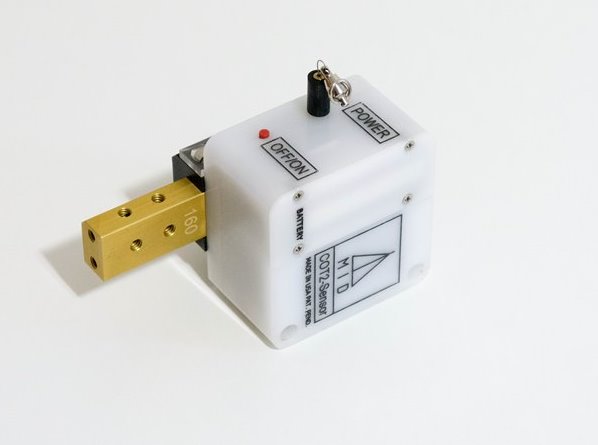
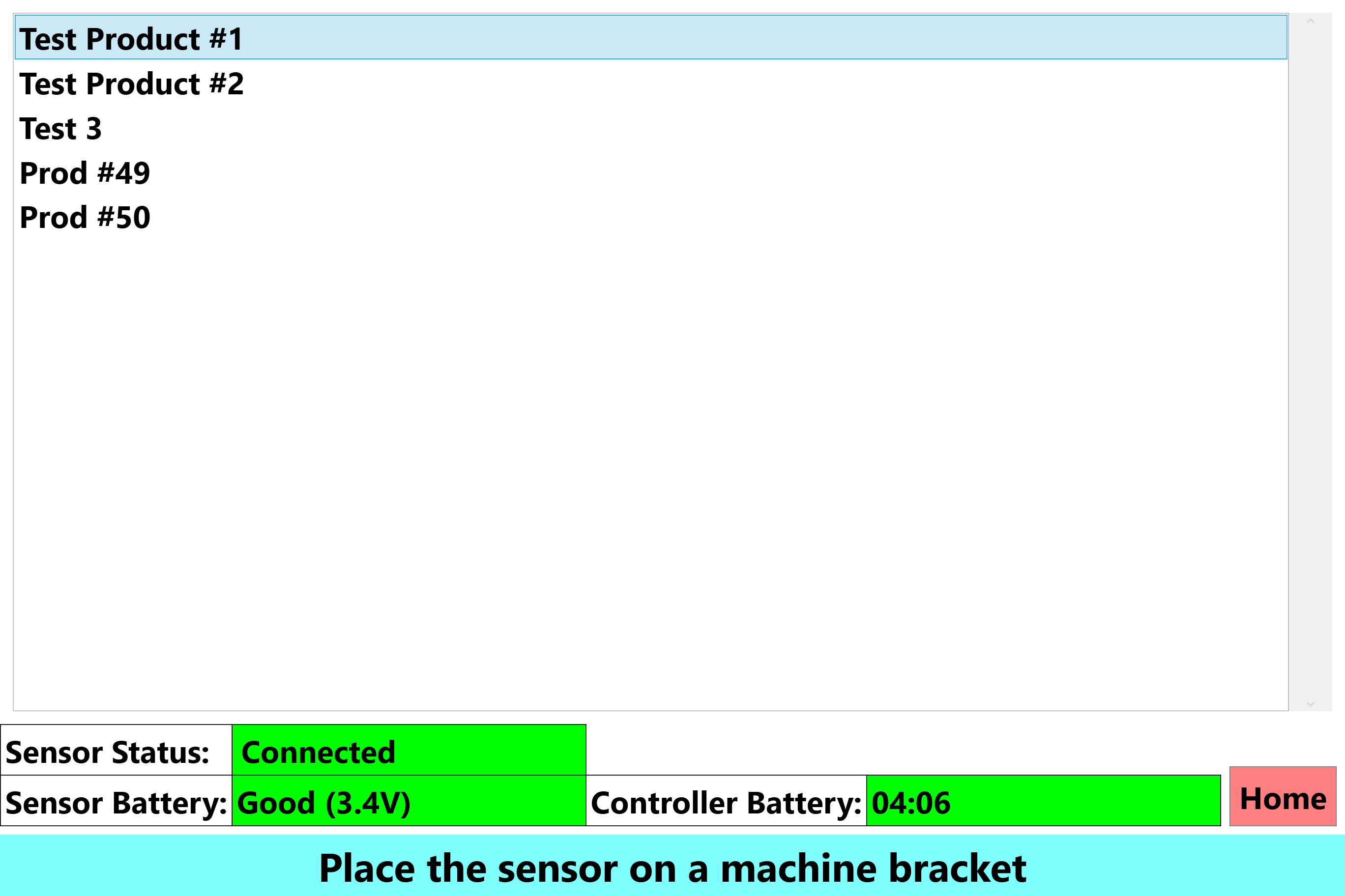
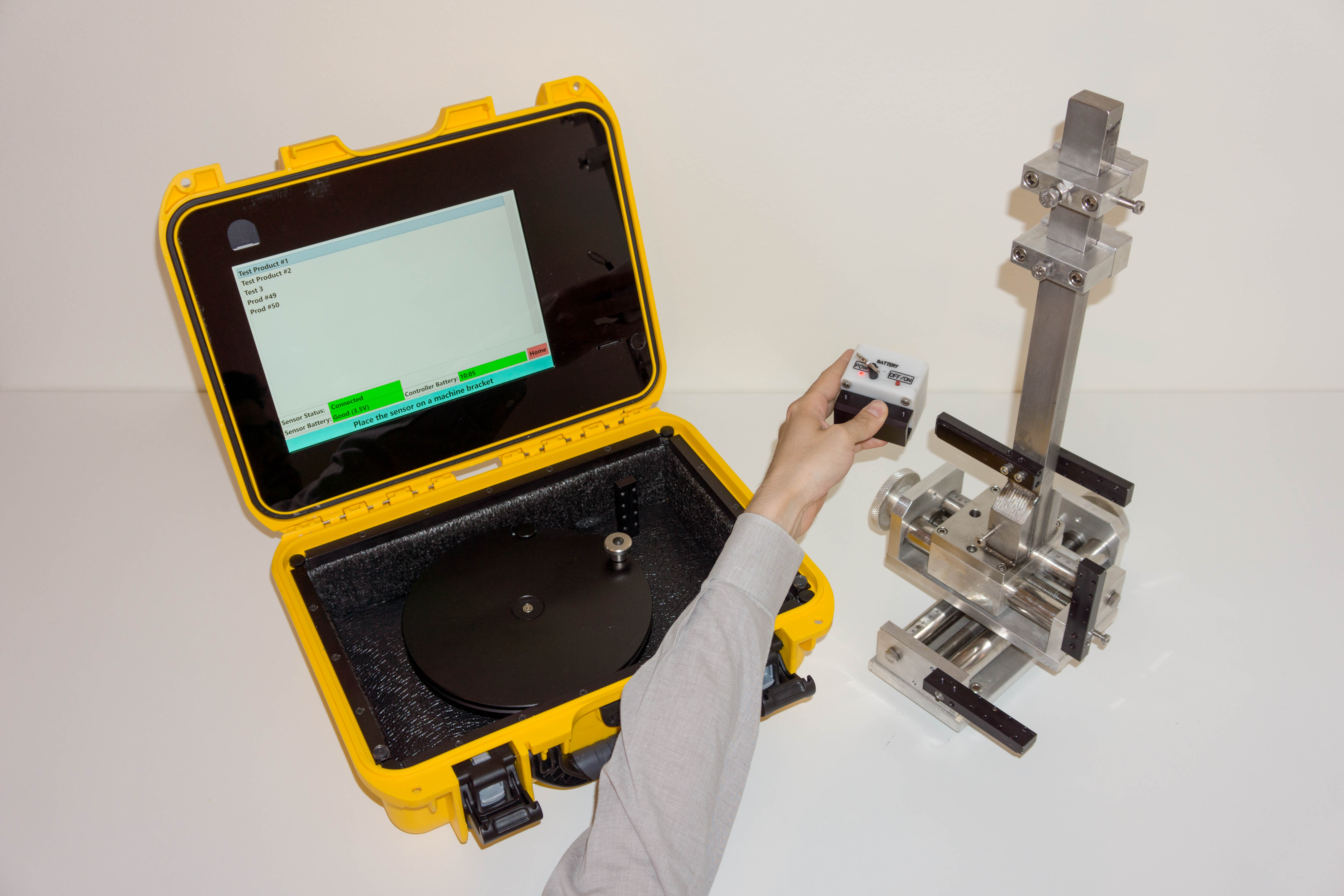
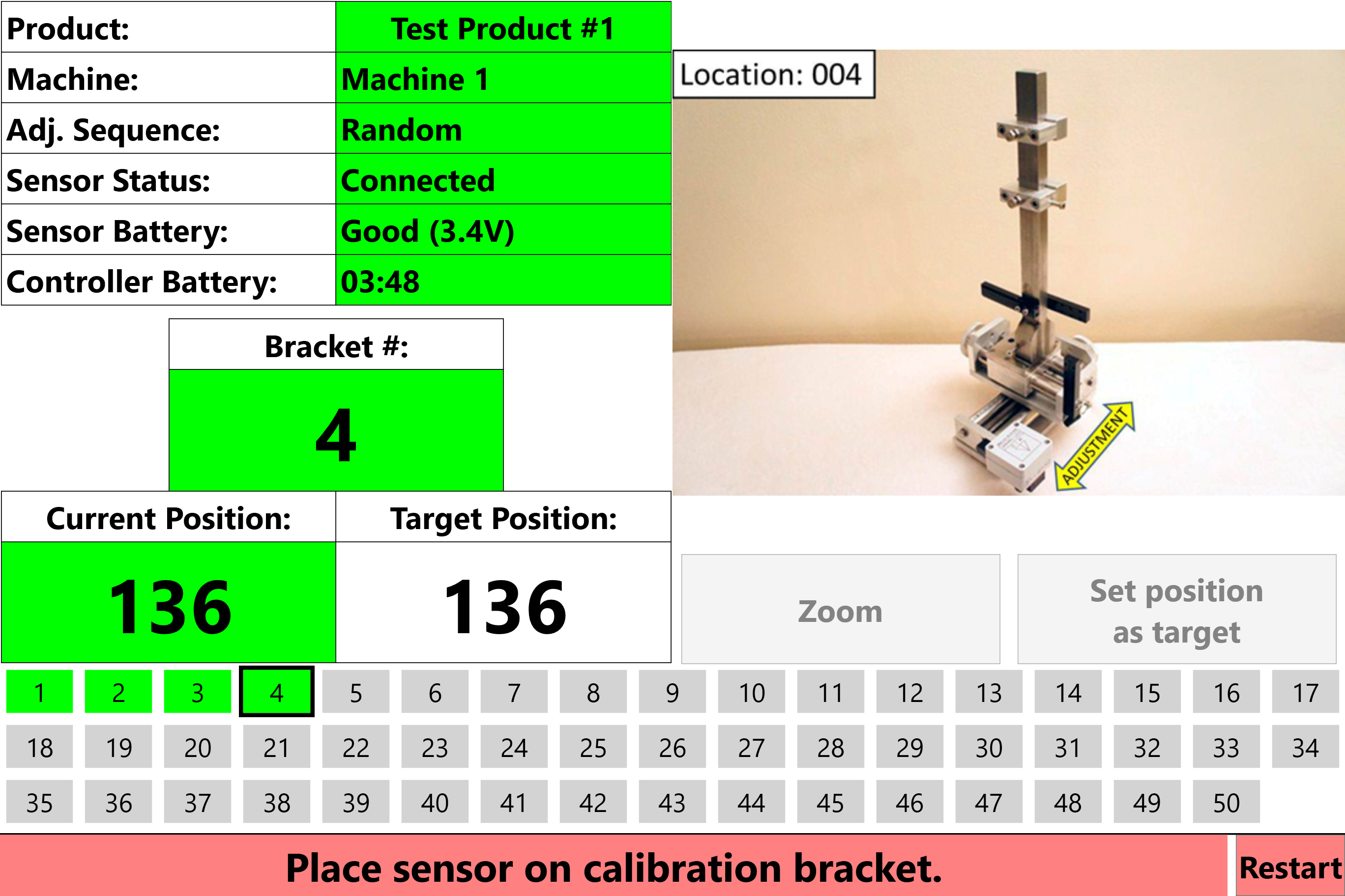
    The operator can now begin using the COT sensor for machine changeover guidance. They should place the COT sensor onto a machine bracket and hook the wire-drawn potentiometer to the designated hook point (for the bracket number).


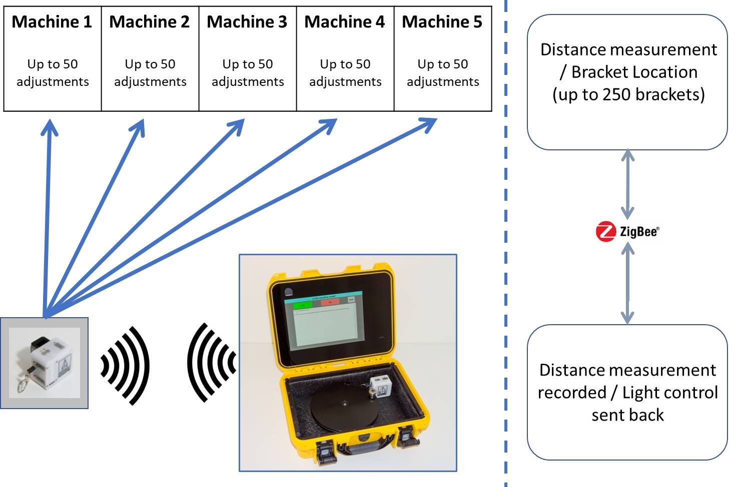
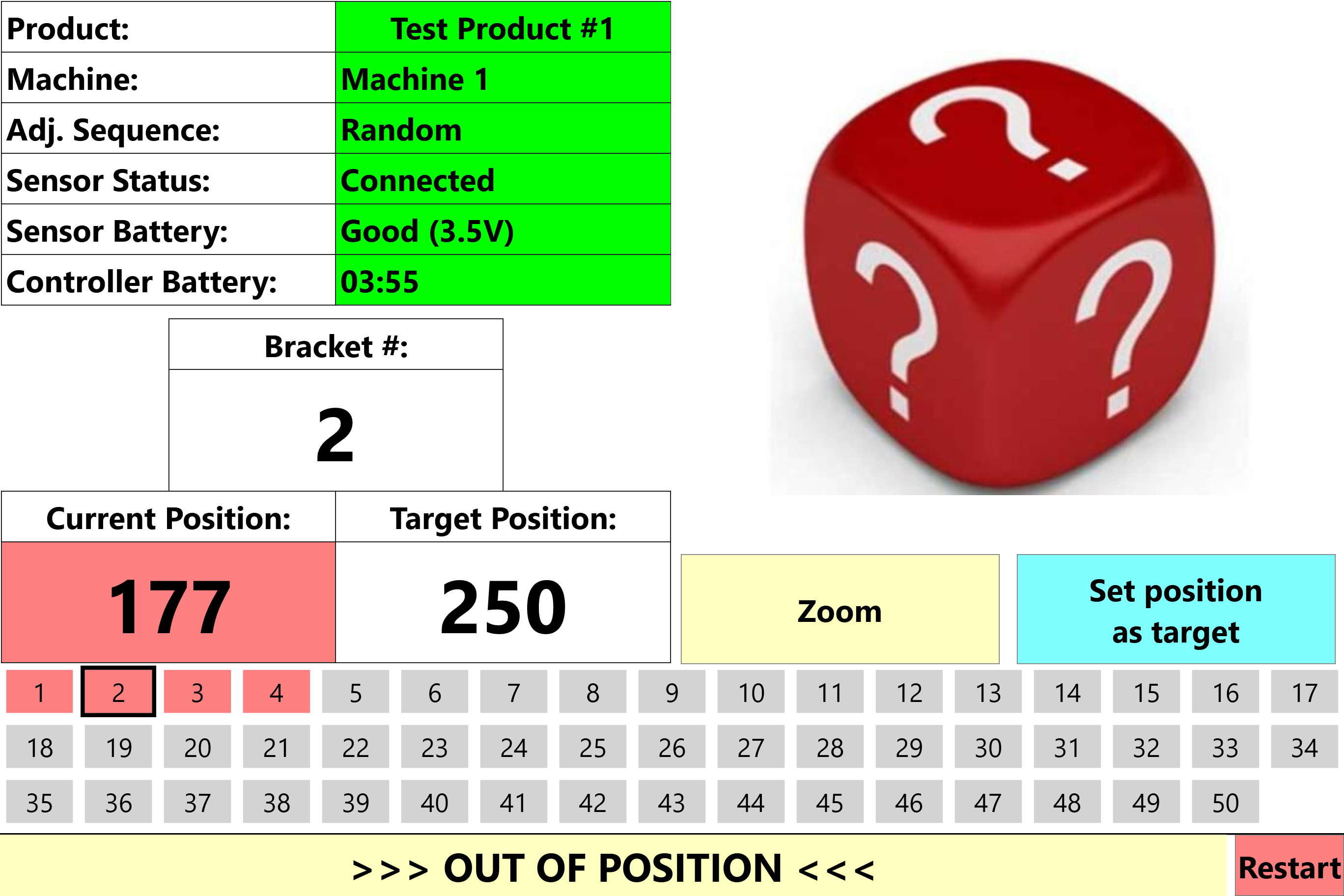
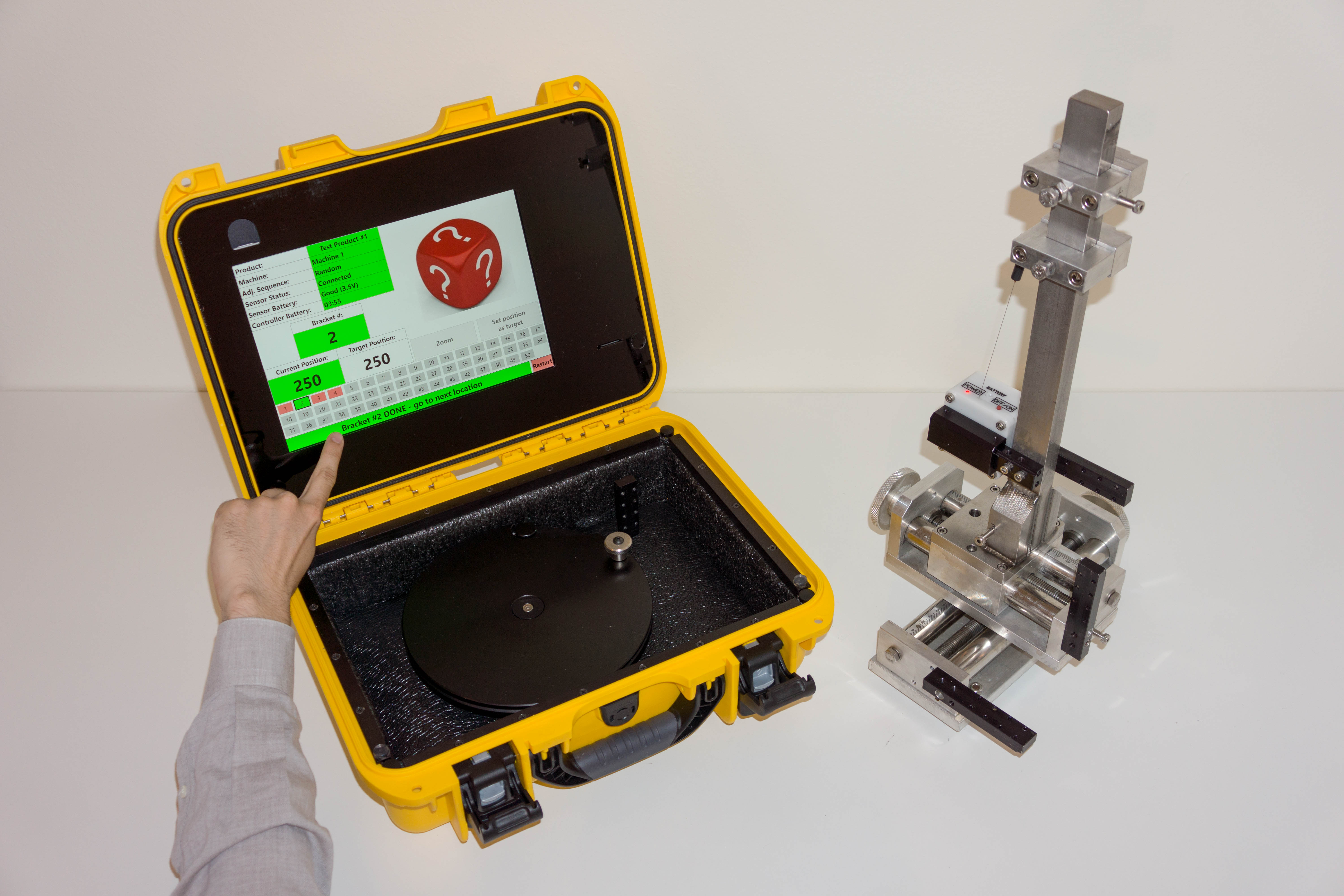
    The software will then display the bracket number (the sensor is placed on), the target position (for the bracket location/machine/product) and the current measurement distance (being read by the COT sensor). The operator will then begin adjusting that machine location until the target position and the current measurement distance are the same number value.


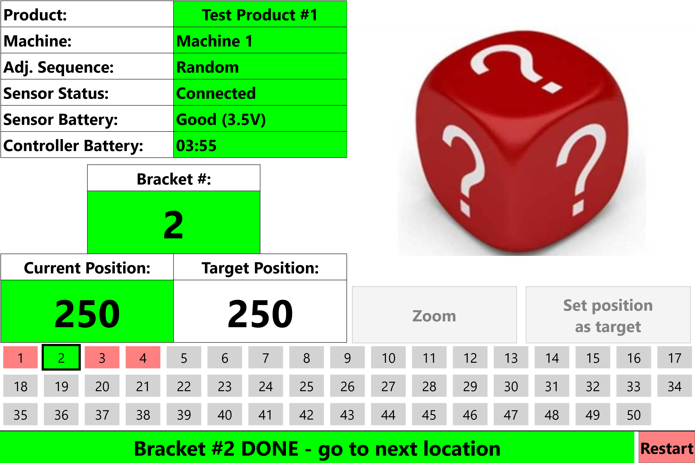
    Once the target position and current measurement distance has been achieved, and held for 5 seconds, the system will consider that bracket location adjustment has been successfully completed. At this point, the operator can remove the COT sensor from the completed bracket location and proceed to the next bracket adjustment location.


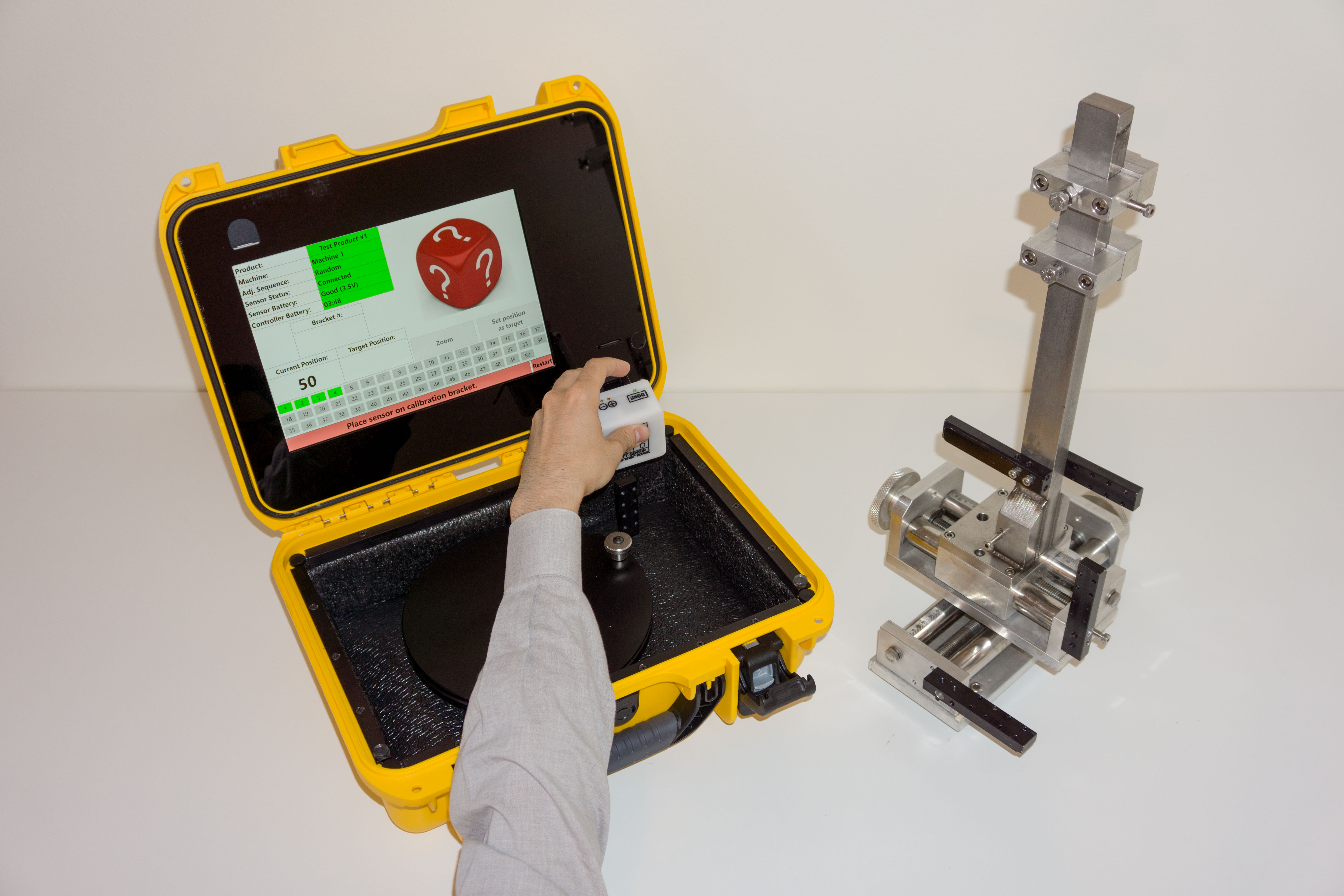
    The operator will continue to each bracket adjustment location for the machine being adjusted until all configured bracket locations have been completed. Upon completion, the operator is instructed to return the wireless COT sensor to the calibration bracket for powering down and safe storage.


    Upon completion and successful return of the wireless COT sensor, the Changeover Tool creates a backup file with a date and time stamp.